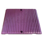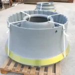
A VSI rotor contains more wear positions than its most visible tips. A photograph of a tip tells little about the back-up tip, feed tube, distributor plate or wear plates fitted around it. Before reordering, identify the rotor version and the pieces changed at the last maintenance stop; some configurations also use anvils.
Follow the material through the rotor
VSI crushers operate through a distinct mechanism that differs fundamentally from horizontal shaft impactors. Maintenance teams often confuse HSI blow bars with VSI rotor tips, yet these components serve different functions and possess unique geometries. A VSI setup utilizes rotor tips, backup tips, cavity wear plates, and upper or lower wear plates to manage material flow. Additionally, the system incorporates a feed tube, distributor plate, and trail plates to direct rock into the crushing zone. Confirming that the requested parts match the VSI configuration is the first step in maintaining the integrity of the rotor assembly.
Identify the tip and plate positions
The primary identification challenge involves the variation between rotor designs and machine versions. A reference code serves as an identifier for a specific part number, but it does not function as proof of interchangeability across different rotor models. Buyers should request the exact rotor model number and the machine serial number from the maintenance logs. Because VSI wear parts are engineered for specific rotor configurations, using a part designed for a different version can lead to mechanical failure or improper material flow. Always cross-reference the part number against the specific manual provided by the original equipment manufacturer.
Use feed conditions when choosing material
Selecting the appropriate material for wear parts requires an analysis of the feed characteristics and operational environment. The choice of rotor tips and wear plates depends heavily on the feed size, the abrasiveness of the material, and the crushability of the rock. Furthermore, the rotor speed significantly influences the rate of wear on the distributor plate and anvils. When evaluating options, request technical data regarding the material composition and its suitability for the specific feed type. Understanding these variables allows for a more informed decision regarding the durability and expected service life of the replacement components.
Check the pieces in the shipment
Upon receiving the shipment, the inspection process should focus on physical dimensions and surface finish compared to the original specifications. Verify that the rotor tips, backup tips, and wear plates match the physical dimensions noted in the procurement documentation. Check the mounting surfaces of the distributor plate and feed tube for any deviations that might affect installation. If the parts do not align with the rotor work and wear limits specified in the machine manual, document the discrepancies immediately. Proper verification ensures that the components are ready for installation without requiring field modifications or adjustments.
List a complete VSI enquiry
Give the machine and rotor version, part position, full public reference if known and quantity for each tip, plate, feed component or anvil. State feed size and abrasive conditions, then ask the supplier what material and inspection evidence it proposes for those positions. Do not combine VSI tips with HSI blow bars on a purchase line. The exact equipment manual governs rotor work, balancing, lifting and wear limits.