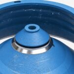
A late tip change can expose the rotor body, turning a routine wear-part stop into a more involved repair. Use this checklist to identify what needs inspection, record the wear pattern and prepare a part number or model-match request before ordering.
The installed configuration determines which parts and limits apply. For a broader introduction to the components, see the VSI crusher parts guide. Follow the machine documentation and site isolation procedures for inspection and replacement.
Map the wear parts before the stop
| Part | Typical location / role | Risk if left too long | RFQ identity tip |
|---|---|---|---|
| Rotor tips / carbide tips / tip holders | Rotor periphery | Rotor body damage or uneven throw | Tip part number, holder part number and set count |
| Anvils / anvil rings, where fitted | Anvil ring or chamber wall path | Shape loss and poorer reduction | Anvil part number and segment count |
| Feed tube / distributor / upper wear parts | Feed path into the rotor | Feed scatter and uneven tip wear | Tube and distributor part numbers |
| Wall liners / wear plates | Chamber walls | Shell exposure and localized wear | Plate part number and position map |
| Backup / cheek-style segments, where fitted | Supporting wear stack | Wear spreading to underlying parts | Position and thickness |
Not every rotor uses every listed component. Map the actual positions and take photos before removal, then label removed parts so each wear face can be linked to its position.
Change-out triggers
Use the documented wear limits for your installation. The signals below are inspection prompts, not universal replacement dimensions.
| Signal | Likely part(s) | Action |
|---|---|---|
| Tip height or edge below the plant limit | Tips and possibly holders | Change tips; inspect holders and their seating |
| Product shape or throughput drops with comparable feed and operating settings | Tips and anvils, where fitted | Measure both before ordering only one; investigate other process causes too |
| Uneven wear at one position | Feed tube, distributor and tips | Inspect the feed path and correct the cause before fitting a full tip set |
| Wall hot spots or liner reaches its wear mark | Wall liners | Map positions and replace the affected set or marked zones as the maintenance plan requires |
| Vibration or imbalance after tip work | Tip seating or a missing tip | Stop and inspect seating and completeness before further operation |
| Cracked high-chrome components | Tips or other cast wear parts | Review impact, tramp and alloy suitability; retain photos for the RFQ |
A change in product shape is a clue, not proof of a worn anvil. Compare feed, settings and wear measurements before deciding which parts to replace. Not all tip designs use the same materials: confirm the construction of the actual tip and holder before selecting an alloy.
Choose an alloy direction for the duty
These are indicative starting points, not a specification or a life guarantee. Confirm that the material is suitable for the specific part design, mounting and operating duty.
| Duty snapshot | Starting direction | Watch-out |
|---|---|---|
| Abrasive sand or manufactured sand with controlled feed | Consider high-chrome cast wear parts or a suitable hardfacing path | Tramp and uncrushables can crack brittle components |
| Mixed quarry rock with occasional tramp | Consider a tougher suitable material, such as a manganese or martensitic option where appropriate for the part | Balance wear resistance against breakage risk; do not assume every tip can use the same alloy |
| Unknown feed | Document rock, feed size and metal risk before changing material | Photos of failed parts help distinguish cracking from abrasion |
The wear-parts materials guide covers alloy families. If hardness is part of the purchase specification, agree the material, test location, method and acceptance range before ordering; see hardness testing. A high reading alone does not establish fitness for impact.
Stop for seating or balance concerns
Isolate the machine under the site procedure before inspection. If vibration appears after work, or a tip is missing or improperly seated, stop and have qualified maintenance personnel check the assembly against the machine instructions. This checklist is not a rotor rebuild or balancing procedure. Do not continue running simply to use up the remaining wear material.
VSI wear kit RFQ checklist
| Field | Send |
|---|---|
| Identity | Part name and part number if known; position and hand where applicable |
| Machine | Model, series and rotor configuration for model match |
| Set | Tips per rotor, anvil segment count, and full kit versus partial replacement |
| Duty | Rock or sand, maximum feed size and known metal contamination |
| Wear evidence | Photos of tips, anvils and tube; hours or tons on the last set if known |
| Alloy preference | High-chrome, a suitable tougher option, or request a recommendation |
| Quantity and destination | Number of pieces or sets, port and Incoterm if known |
A number is a starting point for identification, not proof of interchangeability. Include a drawing revision or sample details when fit is uncertain. For planning factors, see casting MOQ and lead time.
FAQ
Should tips or anvils be replaced first?
Measure both against the applicable limits and inspect the rest of the wear path. Replace the part that has reached its limit; a change in output alone does not identify the culprit.
Should I order a full set or only worn positions?
Check the maintenance instructions and wear across all positions. A full set may be needed for a consistent assembly; partial replacement should be assessed for seating and balance by the maintenance team.
Is a tip part number enough for model match?
It helps, but also send the rotor configuration, holder reference and set count. Similar-looking parts may fit different assemblies.
Will high-chrome always last longer?
No. It can suit controlled abrasive feed, while impact or tramp may cause cracking before the available wear material is used.
What is the lead time for a VSI kit?
It depends on the exact parts, tooling, material, quantity and inspection scope. Ask for a quote against the complete kit list and destination.
Is sand treated differently from mixed rock?
Yes. Abrasion, feed size and metal contamination can differ substantially. Describe the actual feed and ask for a material recommendation for each position.
Send the checklist and photos to info@gubtcasting.com or use the contact form for a GUBT factory review of the part number or model match.